This tutorial not only describes the concept of setup and hold time, but also explains why setup and hold time are required in digital IC design.
Flip-Flop's Setup and hold time are also one of the most common interview questions for IC design engineers. To facilitate the understanding of setup and hold time, it is recommended to check out the explanation of flip-flop schematic and how it works: here
What is Setup Time?
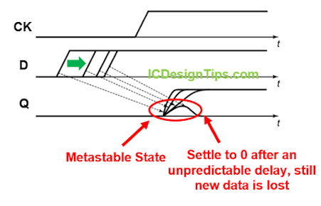
Setup time is the required time duration that the input data MUST be stable before the triggering-edge of the clock. If data is changing within this setup time window, the input data might be lost and not stored in the flip-flop as metastability might occur. What is metastability? When setup and hold time requirements are violated, the flip-flop state becomes unstable, and after an unpredictable duration, the state of the flip-flop can settle either way (1 or 0). This scenario is known as metastability. As shown in the following diagram, output Q1 passes through the slow logic and arrives late at the input D2 of FF2, which leads to setup time violation and the loss of the new data.

Credit: Cadence Design Systems
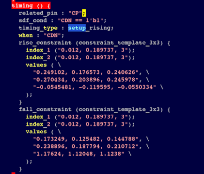
How do EDA tools know the setup time requirement for each flip-flop in the standard cells? The answer is the timing library .lib. It always comes with the PDK (Process Design Kit). In case that you design your own flip-flop circuit, you need to characterize the timing of the Flip-Flop and provide this timing library during the chip implementation. The tools used for timing characterization are Liberate for Cadence EDA or SiliconSmart for Synopsys EDA. Below is an example of setup time in the timing library. Basically, it is a lookup table to provide different setup time based on input and clock transitions.
But, Why Setup Time is Required? How Does Setup Time Violation Cause Metastability?
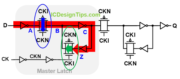
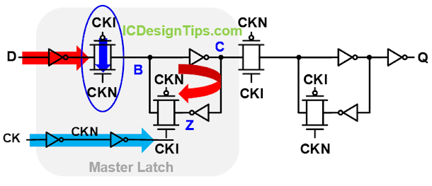
As explained in the previous flip-flop tutorial, during the low phase of the clock, new data will be set up in the master latch. As soon as the clock goes high, data will be latched into the master latch and pass to the output. But, why setup time is required? why does metastability occur? The reason is that D must arrive at Z before the clock goes high switching OFF the input transmission gate (TG) and ON the second TG (the loop is formed) so that the new data (from D) can correctly be latched in the master latch. Therefore, D must be stable long enough (setup time) to travel from the input through the three inverters/input transmission gate and reach Z before the clock goes high. If D arrives too late only at A before the input transmission gate is OFF, the new data has not even arrived inside the latch so that the new data lost is obvious. If D arrives late and only reaches node B or C in the master latch before the rising edge of the clock, node Z still stores the previous data and the contention between new data at B/C and previous data at Z occurs at the master loop. The contention causes data metastability and after an unpredictable delay, the flip-flop state can settle in either way (0 or 1) so the new data might unexpectedly be lost and not stored in the flip-flop latch as shown in the timing diagram below. That's why setup time is required so that the new data can be reliably stored in the flip-flop without metastability.
What is Hold Time?
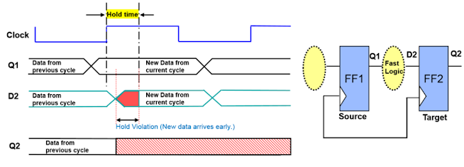
Hold time is the required duration that the input data MUST be stable after the triggering edge of the clock. Similar to setup time violation, hold time violation will cause data metastability and new data might not be correctly stored in the flip-flop. As shown in the following diagram, output Q1 passes through the fast logic and arrives too early at the input D2 of FF2, which leads to hold time violation and metastability.
Credit: Cadence Design Systems
Similarly, hold time of flip-flops are given in the timing library. Below is an example of hold times in a timing library.

But, Why Hold Time is Required? Why Does Hold Time Violation Cause Metastability?
As discussed in the previous flip-flop tutorial, when the clock goes high, the input transmission gate is switching OFF to isolate the input D from the master latch. However, the transmission gate is not turned OFF immediately after the rising edge of the clock because the clock needs to travel through the two clock inverters and the gate itself also takes time to close. Therefore, the input data MUST not be changed until the transmission gate is completely OFF. Otherwise, the change in D during the hold window (as the input transmission is still not OFF yet) would influence the stored data (B, C, Z) in the master latch. If input data change during hold window arrives at B or C, the contention between changed data (B/C) and the stored data (Z, set up before the rising edge of the clock) would cause the metastability in the master latch. Then, the stored data might be lost if the metastability settles to unexpected data. Of course, if the change in D arrives at Z before the input transmission gate is OFF, the new data (changed) will be stored in the latch instead of the currently stored data. That's why data hold time is required after the rising edge of the clock so that the stored data (set up during the low phase of the clock) will be kept reliably in the master latch without metastability.
To understand more about flip-flop schematic and operation, read here.
To understand the setup time equation, check here.
To understand the hold time equation, check here.
Check here on how to fix setup time violations.
Check here to understand the setup and hold slack.
Check here to understand CDC issues in digital IC design.

Comments
Post a Comment